How implicits succeed where B-reps fail
Written by nTop
Published on March 28, 2019
As previously described, the B-rep modeling used by most precise and mesh-based CAD and graphics systems works well for low complexity parts and most traditional manufacturing processes. For any experienced CAD user, the promise of 100% reliable and accurate operations might seem too outlandish to be credible. Building on the previous post’s description of the representations themselves, let’s see why implicits deserve to work and B-reps don’t.
There are two main techniques of representing shapes in 3D CAD systems: boundary representation (“B-rep”) and implicit modeling. We discussed the details of these at the beginning of the Implicit Modeling series.
As previously described, the B-rep modeling used by most precise and mesh-based CAD and graphics systems works well for low complexity parts and most traditional manufacturing processes. However, advanced manufacturing requires:
- Incorporating diverse inputs of varying fidelity to produce precise output
- Synthesizing highly complex, functional, mesoscale beam and lattice geometry
- Automated, verifiable processes for knowledge-driven and mass customized products
For any experienced CAD user, the promise of 100% reliable and accurate operations might seem too outlandish to be credible. Building on the previous post’s description of the representations themselves, let’s see why implicits deserve to work and B-reps don’t.
Containment
The fundamental job of any solid modeler is to know if a point is inside or outside a shape. It’s also common to ask whether a point is within a tolerance of the boundary.
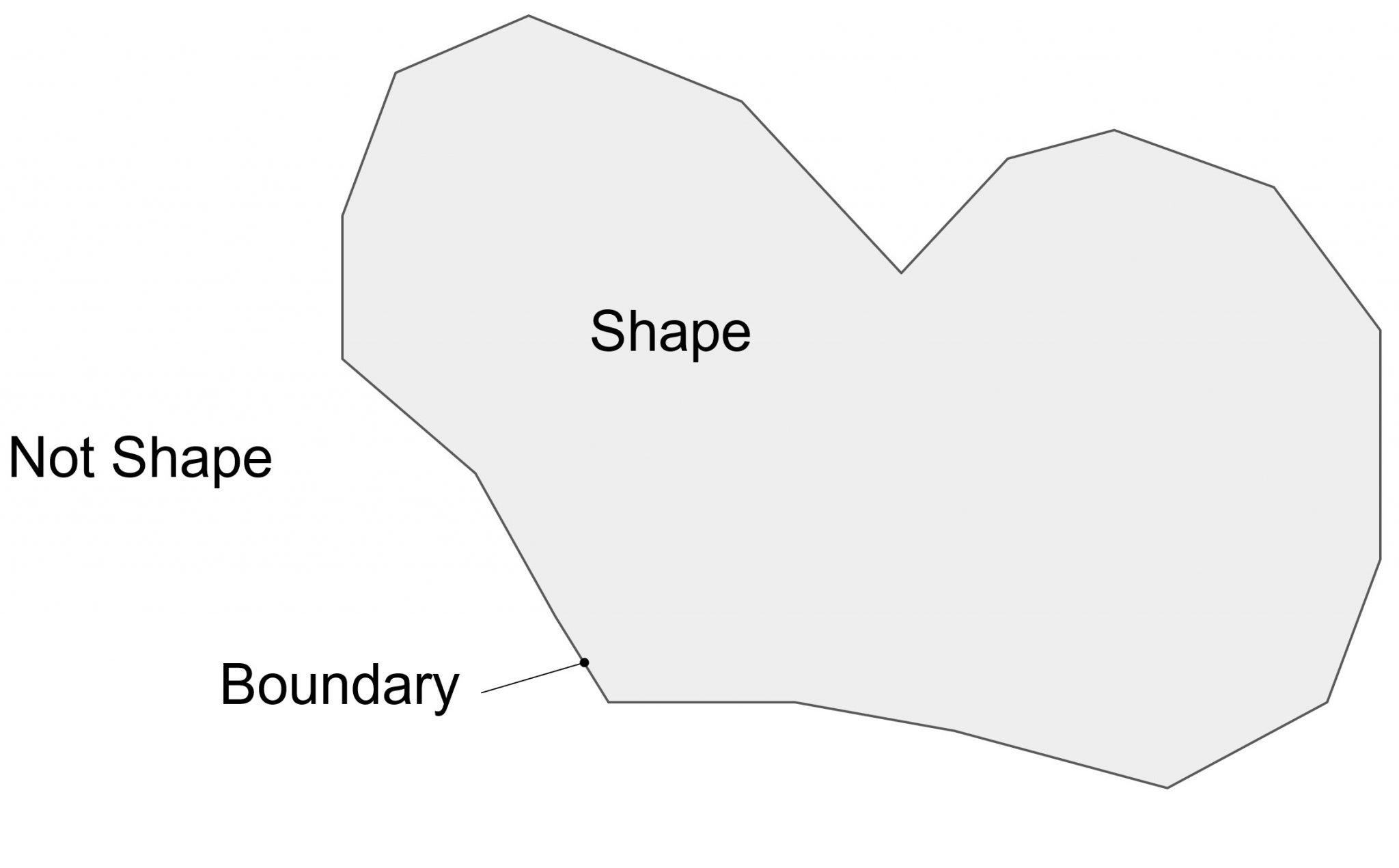
Solids have an inside, an outside, and a boundary that separates them into regions.
For B-rep modelers, answering the containment question means checking a point against every piece of topology in the model. A common approach is to create a ray that begins with the point in question and travels in any direction. If the number of intersections is odd, the point is inside the shape, otherwise it is outside.
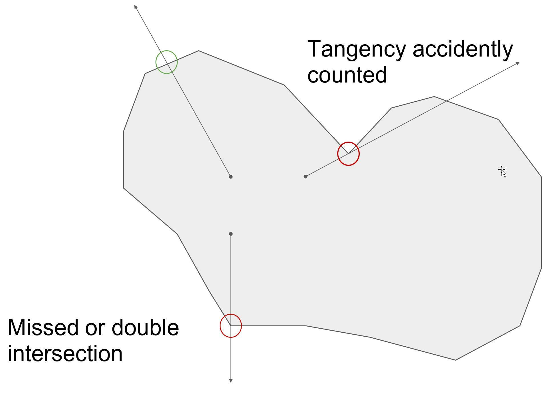
Using rays to compute containment can fail when the ray passes through an edge or is tangent to an edge or face.
Such a calculation is expensive and error-prone, as faces can get missed or double counted if struck near their edges or near tangent to edges or faces. Although new techniques mitigate this problem for mesh modelers, B-rep and mesh modelers still struggle with this basic test.
Implicits use a sign convention to designate inside versus outside, so containment is a trivial test. Values closer to zero are closer to the boundary, so one can establish if a point is within tolerance of the boundary. In both accuracy and performance, implicits are better at the containment test.
Offsetting
In the previous post, we saw how offsets were also directly encoded into distance fields. What happens if a B-rep needs to be offset? Let’s examine a concave region of a faceted shape.
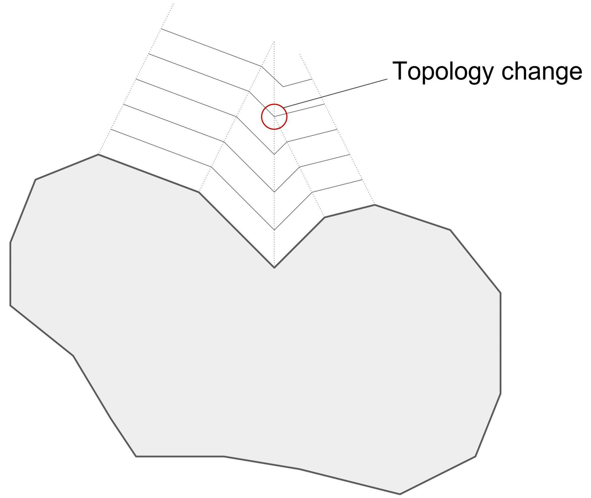
Offsetting four curves, we see that the topology changes where lines swept by the vertices intersect. These swept lines are called “medial axes” or “cut loci,” depending on whether inside or outside, intersect.
When we offset a 2D profile, as depicted above, or a 3D solid, a B-rep modeler needs to make sure that every face doesn’t start intersecting with any new faces. When, in the course of a modeling operation, such an event is encountered, it has to be handled as a special kind of “topology change.” Most modern mesh and B-rep modelers can only achieve modest offsets for real-world geometry, as every kind of topology change must be handled as a special case. Precise modelers further complicate the problem because analytic geometry like cylinders and tori can vanish completely when offset inward, and bounded geometry like spline surfaces may become internally self-intersecting, possibly in invisible areas outside of the trimming loops of the face.
Clearly, offsetting B-reps can be very complicated depending on the geometry and topology. For example, consider an operation like generating a series of “onion skin” offsets of a mesh to produce a sequence of surfaces for a five axis additive application. For a complex shape, producing one offset at manufacturing resolution could bring the most robust B-rep modelers to their limits.
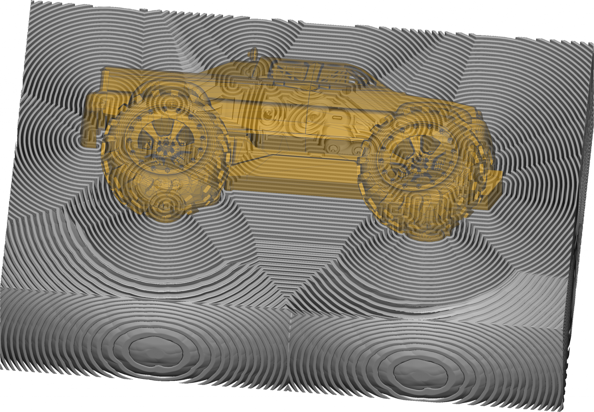
In contrast, by using implicit modeling, nTop easily produces all of the offset layers at manufacturing resolution.
Onion shells generated from a toy truck. This simple illustration shows the implicit produced by a periodic function of the truck’s distance field. The roughness towards the bottom is the result of the precise offset of the treads of the tires.
Boolean operation failures
Finally, let’s observe why B-rep modelers have difficulty with booleans. To do so, we’ll use the term “manifold,” which basically means that something locally looks solid in any number of dimensions. When a CAD system tells you it needs a closed sketch profile, it’s asking for a one-manifold. A solid is two-manifold, and a surface body is two-manifold everywhere except the open edges.
For sketch profiles, to be manifold, every curve endpoint in the profile must meet exactly one other curve endpoint. For a solid, it means every edge joins exactly two faces.
Most B-rep modelers don’t let you perform a boolean union of solids where the result might not be manifold.
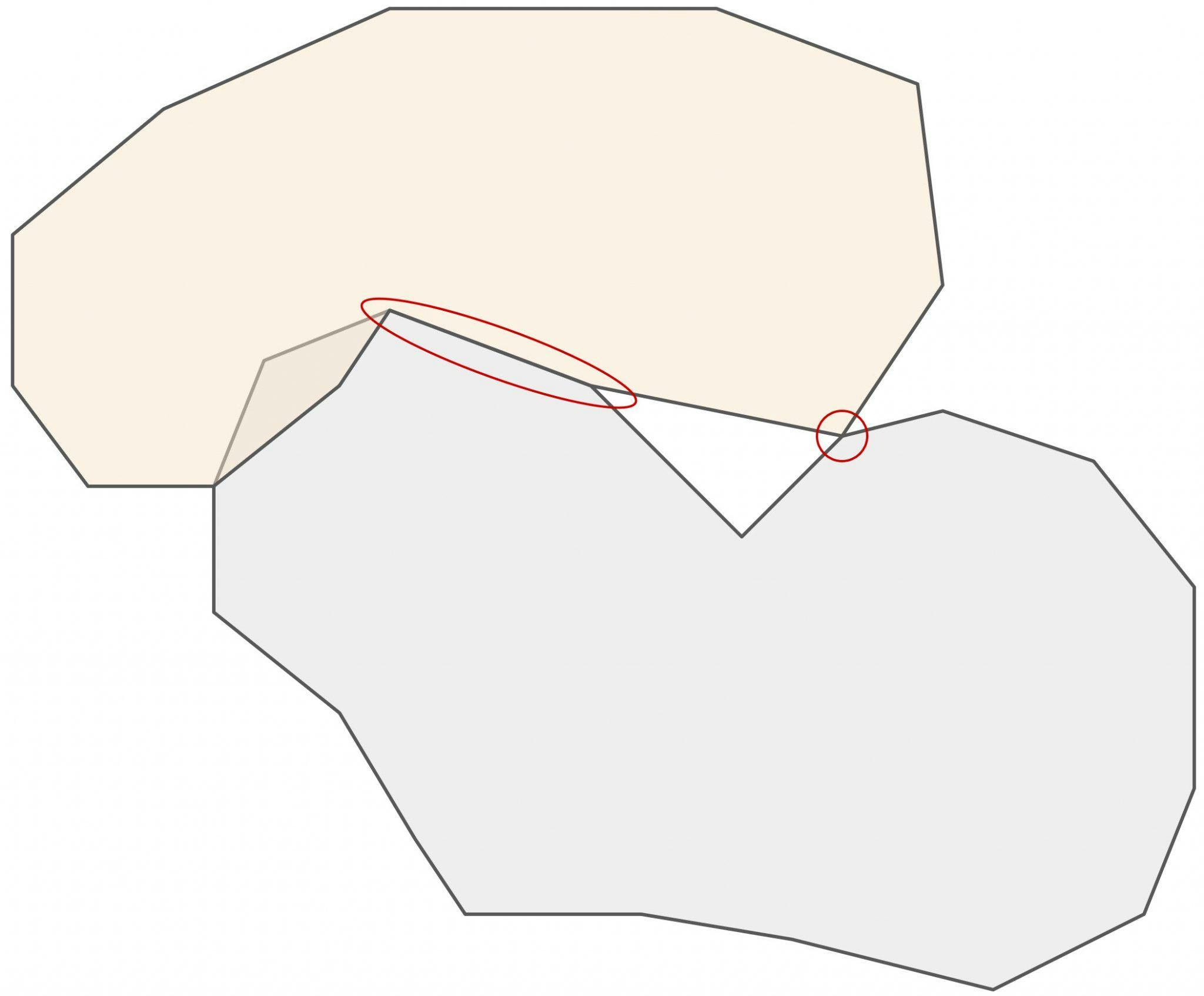
Two regions where booleans can fail in B-rep modelers. The circled region shows a non-manifold result, as four faces would touch one edge. The oval-shaped region shows facets at risk of geometric errors.
The types of errors shown above demonstrate near-coincident geometry. In many cases, such as with meshes generated from concentric cylinders and other mating surfaces, many small regions of overlap or air gap may be perceived by the modeler where none is intended. Similarly, meshes produced from scan data or CAD assemblies can have similar overlapping chatter and fail to boolean or produce noisy results.
How do booleans work with implicits? Let’s reuse the ‘R’ from the previous implicit post with its reflection and look at both the boolean union and intersect.
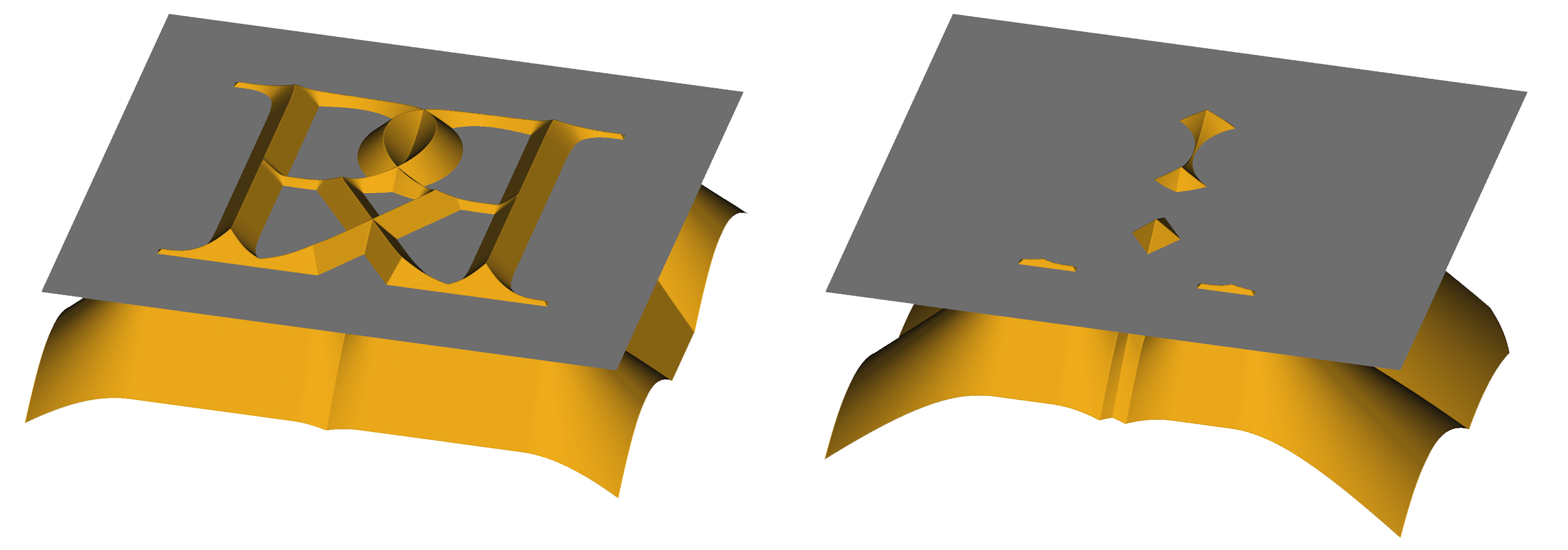
The boolean union (min) and the intersection (max) of the 2D R shape and its reflection, visualized as 2.5D surfaces of the 2D distance filed. (In these illustrations, with our sign convention, positive is below the plane.)
What function could give us the intersect or union? Before we continue, we stick with the sign convention that the inside of the part is negative, so in the image above we’re looking at the fields of the Rs upside down. Higher is a smaller value. Therefore, the union of the two Rs is the minimum value of the two functions. Similarly, the intersect is the maximum. (The functions swap if the sign convention swaps.)
Min or max functions always return a value, so booleans always work. Notice that the resulting shape includes all of the important remote data too, so all of the offset information is still stored with the shape. Non-manifold or near-coincident regions are only special cases in the shape of the remote data, and would fade and reappear easily with small offsets.
More operations
To summarize, implicits use a continuous field of signed values, so knowing what is inside, outside, or at the boundary is trivial. Implicit operations are devoid of topology issues, so offsets and booleans never fail. Although the most basic examples, these operations set the stage to why implicit modeling can be 100% reliable for the automated processes and complex geometry demanded by advanced manufacturing.
What about other modeling operations? Are there implicit versions of traditional solid modeling features like extrusions and sweeps? What about rounds, chamfers, drafts, and other features on existing topology? How can these operations be combined with simulation and traditional workflows? We’ll be getting to these topics in future posts.

nTop
nTop (formerly nTopology) was founded in 2015 with the belief that engineers’ ability to innovate shouldn’t be limited by their design software. Built on proprietary technologies that upend the constraints of traditional CAD software while integrating seamlessly into existing processes, nTop allows designers in every industry to create complex geometries, optimize instantaneously, and automate workflows to develop breakthrough 3D-printed parts in record time.
Related content
- VIDEO
Five ways to lightweight in nTop
- VIDEO
Sneak peek into the nTop + Autodesk Fusion 360 integration
- ARTICLE
Optimizing thermal management with conformal cooling to extend operational life
- ARTICLE
Advancing structural performance of aerospace heat exchangers
- VIDEO
Design a spooky Halloween candy bowl in nTop