Topology optimization in a world of fields and implicit geometry
Written by Trevor Laughlin | VP, Product at nTop
Published on April 25, 2019
Manual reconstruction of geometry after topology optimization is generally viewed as a major impediment, and this was the challenge first tackled in nTop software. The resulting smooth geometry is generated in seconds and can immediately be used in downstream modeling, simulation, and manufacturing functions. This smoothing capability, enabled by our implicit modeling technology, provides an integrated, continuous, and automated topology optimization pipeline within nTop software.
Despite the word “topology” in the company name, it may come as a surprise to learn that nTop is not a topology optimization company, per se. Rather, we view topology optimization as one tool within the generative design toolbox that can be used as a component of a larger engineering and product design workflow. In this introductory post we’ll explore how topology optimization exists, in fact thrives, within a framework that utilizes field data, implicit geometry, and block architecture.
Topology optimization and generative design: What's the difference?
Let’s start by clarifying some terms often seen in the industry, most notably generative design and how it is viewed with respect to topology optimization. A brief internet search of the two terms yields mixed results and in general it seems fair to use them interchangeably. At nTop we frequently encounter this semantic confusion with our customers. However, after converging on clear definitions, some in fact do want traditional topology optimization, while many are envisioning a more “generative” technique.
Topology optimization is a technique that has been known for decades [1] and is becoming more practical thanks in part to advances in computational technology and additive manufacturing. The approach is typically formulated as a conventional optimization problem, where an algorithm is used to minimize some chosen objective function subject to several constraints. For example, minimizing the weight of a structural bracket subject to constraints including stress, deflection, or overhang angles in the case of additive manufacturing. Topology optimization problems that are quite complex can be formulated, where they involve multi-objective, multiphysics applications with millions or even billions of design variables [2]. Whatever the scale and complexity, the optimization process is conceptually operating in a continuous design space and attempting to converge on a global optimum while satisfying the known constraints.
What is generative design?
Generative design, in our view, is the larger computational process and workflow built by an engineer for their specific product and application, of which topology optimization is simply one function that can be called. What in part makes nTop “generative” is that these connected workflows can be used to explore the design space, perhaps cycling through different materials, manufacturing processes, functional requirements, or even the basic assumptions built into the process by the engineer. Whether this happens using simple parameter sweeps or more advanced design of experiments, for each iteration the process has generated a new design. We could stop there, but an observation worth noting is that these fully connected processes essentially generate data, and that is the key ingredient to even more advanced algorithms that are emerging. We’ll explore that topic in a future post.
The details of topology optimization
Considering topology optimization as a “function call” and a subset of generative design, let’s explore some of its possibilities within nTop. The examples in this discussion were generated using the Solid Isotropic Material with Penalization (SIMP) method implemented within nTop for a basic compliance minimization problem. For each element in the design space, the optimizer will attempt to find a density value that minimizes compliance (i.e., maximizes stiffness) while satisfying a simple volume constraint.
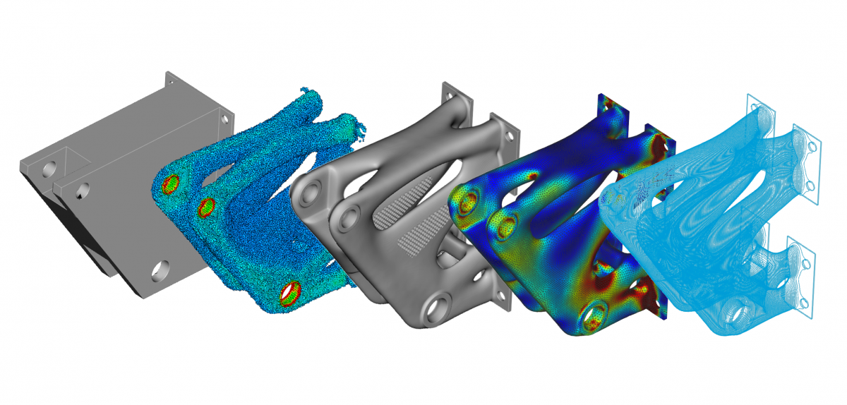
The simple structural bracket example shown in Figure 1 highlights a few key concepts of the optimization process and results. First, a discretized domain is provided as the design space, materials are defined, and boundary conditions are applied much like any other finite element model setup. In this example a volume fraction of 30% was applied, meaning the volume of the optimal design must be less than or equal to 30% of the original.
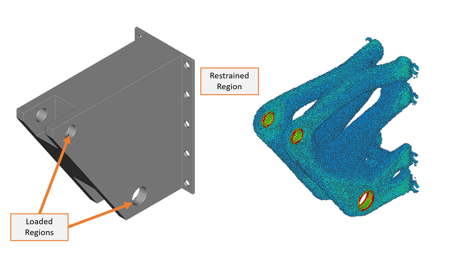
Figure 1: Structural bracket design space and raw topology optimization result.
Interpolation of data fields
Interpreting the results of density-based topology optimization is where most software applications begin to divert from each other. Interpolation schemes, such as SIMP, are used to convert the element densities into continuous design variables better suited for optimization algorithms. This results in element densities that can range from 0 (no material) to 1 (solid material) but also vary in between. This is shown in Figure 1 where the red regions correspond to the highest density and then the values gradually decrease towards zero density (elements not shown), with intermediate results blending between the two. While density-based topology optimization schemes attempt to obtain a binary distribution of material (with no intermediate density values), typical results might still exhibit intermediate densities. With no definitive boundary in the interpolated result, the user is usually left to determine a threshold value between 0 and 1.
At this point, most software will extract an isosurface at the selected threshold value to form a rough approximation of a boundary which can be used as inspiration for final geometry reconstruction. Before we get to geometry construction, note that the most basic result of the density-based optimization process is a spatially varying set of scalar values, a density “field”, which is one of the most fundamental types in nTop as discussed in this post on field-driven design. Figure 2 shows a planar section cut through the original design space which has been filled with an isotruss lattice structure. Here, the density field from the topology optimization is used to directly drive the thickness of the lattice, resulting in thicker lattices in the regions of higher density. This example demonstrates the fundamental idea that topology optimization results, as fields, are naturally represented in nTop and can be used like any other in the software. While this is a very simple demonstration with an isotropic material model, it is the key technique underlying some soon to come physics-based cellular material design capabilities.
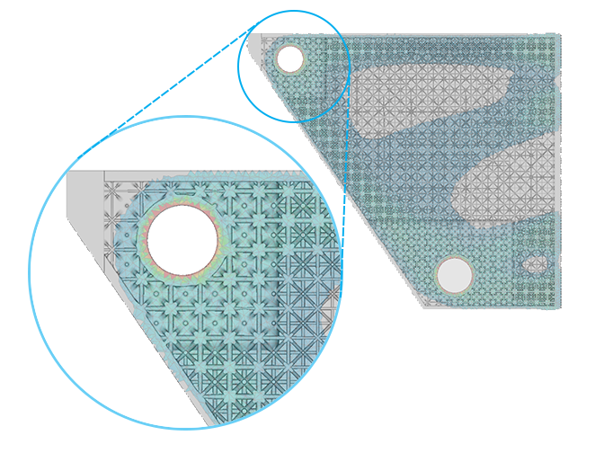
Figure 2: Original design space shelled and filled with a lattice structure using the density field of the topology optimization (shown transparent) to drive thickness.
While the usual goal of topology optimization is to ultimately find some optimal shape, the raw result is typically some inspirational representation and not a definitive geometry ready for verification or manufacturing. It’s at this point an engineer must usually intervene to manually reconstruct a geometric shape which can be a major bottleneck in the workflow. While there do exist some powerful tools to do this manually, the lack of an automated and traceable process will likely not keep pace with the rapid and iterative nature of modern engineering workflows.
Geometry reconstruction
The geometry reconstruction problem is addressed by leveraging nTop’s implicit modeling technology. With only a few inputs, an implicit geometric representation can be derived straight from a topology optimization result. The results of the simple structural bracket example are shown in Figure 3.
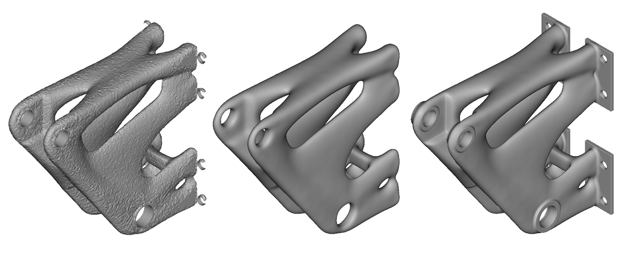
Figure 3: Automated smoothing process (middle) is immediately usable for additional modeling operations (right).
Manual reconstruction of geometry after topology optimization is generally viewed as a major impediment, and this was the challenge first tackled in nTop. The resulting smooth geometry is generated in seconds and can immediately be used in downstream modeling, simulation, and manufacturing functions. This smoothing capability, enabled by our implicit modeling technology, provides an integrated, continuous, and automated topology optimization pipeline within nTop.
An evolving landscape
Whether you’re new to topology optimization or an experienced veteran, you’ve most likely noticed that the technology is moving at a rapid pace. Start-ups have been built around the technology and larger simulation providers are showing renewed interest. nTop is actively engaged with a number of research institutions studying the topic and are amazed by the number of novel techniques being developed. To most software companies, this continuous change may pose a challenge. In contrast, nTop’s block architecture naturally provides an extensible and robust API that can evolve with this improving technology and always deliver cutting-edge solutions. Much like blocks can represent geometry functions, they are also used to construct optimization problems within an extensible framework, allowing engineers to configure the software for the key aspects of their product and workflow.

Figure 4: Automated smoothing, subsequent FE analysis, and contour slices for manufacturing.
Learning more
In this post we have explored some introductory topics in traditional topology optimization and how they manifest in the nTop ecosystem. As previously stated, a common goal of topology optimization is to find an optimal shape that is nearly ready for verification and manufacturing. Rather, the raw result from this method is best viewed as an inspirational representation or one of many acceptable solutions. Either way, there are still data interpretation and geometry construction challenges not easily addressed through conventional techniques. In nTop, since data is represented as a density field, this can drive geometric parameters, including lattice thickness, in a robust way. In addition, geometry reconstruction is no longer a bottleneck because of the implicit modeling technology. These two characteristics in particular allow for a more flexible, automated way of utilizing the process as a viable solution for product design.
To learn more about our perspective on topology optimization, we invite you to check out our webinar on the topic where we'll take a deeper dive into the subject and illustrate how nTop uses fields and implicit modeling to optimize products. We are also excited to announce the addition of the new Topology Optimization toolkit with the release of nTop 2.0 which willow allow you to integrate our simulation and topology optimization seamlessly into your workflow.
References
- Bendsøe, M. P., “Optimal shape design as a material distribution problem,” Structural Optimization, vol. 1, 1989, pp. 193–202.
- Aage, N., Andreassen, E., Lazarov, B. S., and Sigmund, O., “Giga-voxel computational morphogenesis for structural design,” Nature, vol. 550, 2017, pp. 84–86.

Trevor Laughlin
VP, Product at nTop
Trevor Laughlin is the VP of Product at nTop, where he is responsible for leading the product organization and vision, including product management, product design, and technical product support. Before joining nTop in early 2018, Trevor worked in the aerospace industry as a structural engineer and developed conceptual design software used by NASA. Trevor holds a Master of Science degree from Georgia Tech and Bachelor of Science from Iowa State University in aerospace engineering. He currently calls New York City home.
Related content
- VIDEO
Topology Optimization Design for Cast and Injection-Molded Parts
- VIDEO
Lightweighting an impeller for additive manufacturing
- ARTICLE
Efficient thermal and fluid management strategies for aerospace heat exchangers
- VIDEO
Lightweighting a centrifugal pump in nTop
- WEBINAR
Lightweighting aircraft seat legs with AM