Structural optimization: 7 design tips for lighter designs
Written by nTop
Published on January 26, 2022
Lightweighting means more than just reducing mass. Through smart design techniques, you can maximize product functionality and minimize costs. Here are seven design tips for efficient structural design.
Applications
Key Software Capabilities
- Topology optimization
- Lattice structures
Structural optimization is an essential part of the design process while engineering hardware products. As a designer, you have to make tradeoffs to balance multiple design objectives, including cost, materials, and manufacturing constraints.
Luckily, the fundamental design tools in an engineer’s arsenal are very similar whether you're designing products for additive manufacturing or a traditional process. They include modeling techniques like latticing, shelling, perforation patterns, ribbing, and simulation-based methods, like topology optimization.
The following design tips will help you tackle your design optimization problems. You will also find links to video demos and tutorials throughout the article to show you how to apply these techniques.
#1 Use the “shell & infill” method as the benchmark
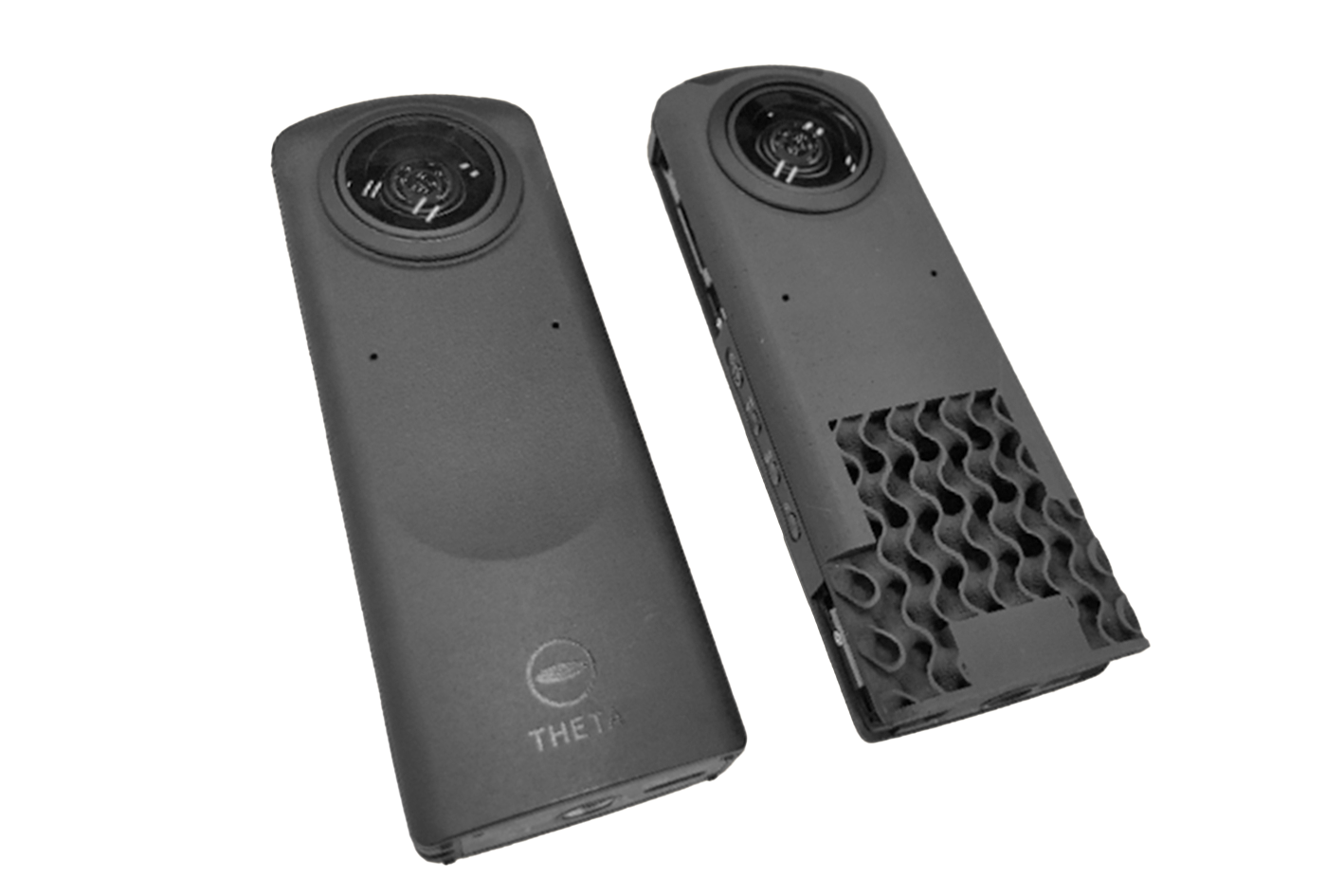
The “shell & infill” approach is one of the most common ways to reduce the weight of additive manufacturing parts. It applies to any 3D printing process — from extrusion-based technologies and resin 3D printing to metal and polymer powder bed fusion.
The shell bears the majority of the loads, while the internal lattice provides extra stiffness and reduces the likelihood of failures during manufacturing.
Despite its simplicity, the “shell and infill'' method is very effective and should always be your starting point — especially when you need to preserve the external shape of your part. It is commonly used in additive manufacturing production and can lead to a weight reduction of more than 60%.
Pro Tip: Don’t forget to add holes or openings for powder removal or resin evacuation.
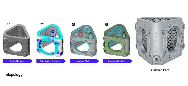
This key component of DMG MORI’s industrial automation robotic system was redesigned using the “shell & infill” approach — it is 62% lighter and has 60% fewer components than the initial design.
#2 Vary the thickness of a shell using simulation data
For structural components, varying the thickness of the shell ensures that stresses can remain within the safe limit at critical locations without adding unnecessary material throughout the part. There are two main ways to create a refined shell of variable thickness.
One way is to manually assign a thickness to each surface of your part, thicken them separately and then combine them using a boolean operation.
Alternatively, you can run a structural analysis on your original part — for example, a static analysis — and then use the results to create a shell that smoothly transitions between two predefined levels of thickness; thicker where stresses are high and thinner where stresses are low.
Here’s a video that shows you how to apply step-by-step simulation-driven variable shelling Field-Driven Design.
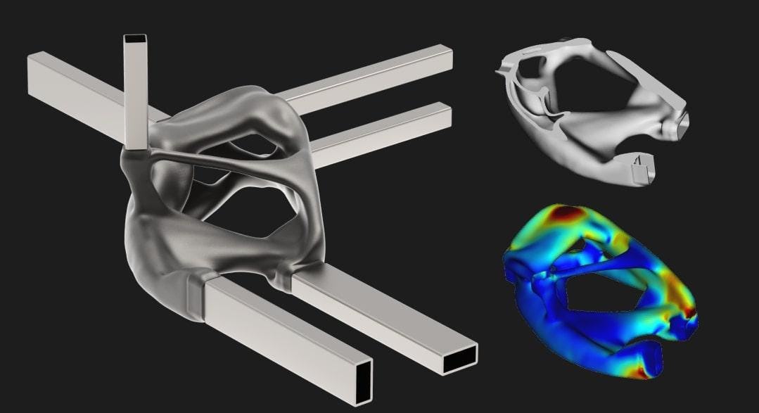
This automotive bracket was first topology optimized and then shelled to improve its crashworthiness — a static analysis is driving the thickness of the shell wall.
#3 Create a graded lattice driven by topology optimization
You can also use a similar field-driven design approach to control other design elements. In the example below, the results of topology optimization on this ALCOA bracket were used to drive the thickness of the internal lattice.
This hybrid approach combines the benefits of the “shell & lattice” approach (easy manufacturability, compliance to an external shape, and so on) while grasping some of the high stiffness-to-weight ratios of topology optimization.
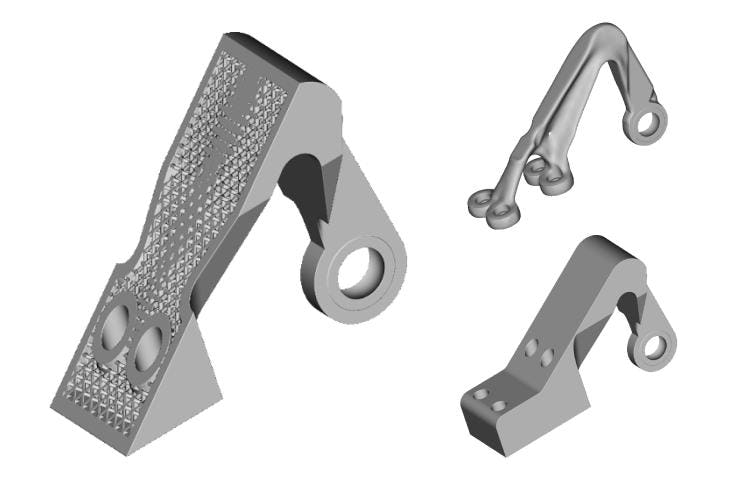
The topology optimization results were used to drive the thickness of the internal lattice of this ALCOA aircraft bracket.
#4 Let simulation inform your lattice selection
There are multiple variables that you should consider when designing a lattice structure — unit cell type, cell size, beam or wall thickness, cell map orientation, and so on.
An iterative simulation-driven approach is the fastest and cheapest way to make the best design decision. There are three main methods that you can use to simulate a lattice.
FE-based simulation
A finite element analysis will provide the most accurate results, but it is 10x to 60x times more time-intensive than the other methods.
Beam-based simulation
An FE simulation that uses only beam elements will provide quick and (relatively) accurate results — but it’s not an option for TPMS lattices (like gyroids) or plate-based lattices (like hexagonal honeycombs).
Homogenization
This is the quickest method to approximate the behavior of a lattice-based on the geometry of a single unit cell. However, it is the least accurate for smaller lattices with less than a few hundred unit cells.
Pro Tip: Run a small computational Design of Experiments first using beam elements or homogenization and then run a detailed FE analysis — or a test print — to validate the results.
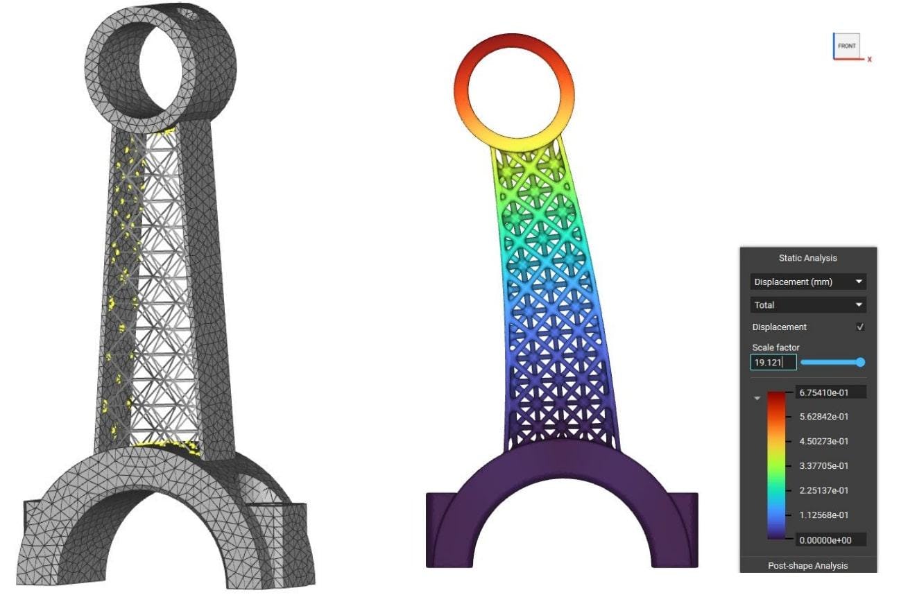
The lattice of this bracket was optimized following an interactive design process that was automated using scripting in nTop Automate.
#5 Perform a sensitivity analysis for “optimum” topology optimization
Speaking of topology optimization, here’s something that you should never forget:
The results of topology optimization are only as good as the boundary conditions used to produce them.
There are many knobs to turn when running an analysis using topology optimization. Despite the name, not all results are equally optimal. For this reason, running a sensitivity analysis to tweak important input parameters is always a good idea.
For example, when you apply different boundary penalties or stress constraints, the outcome of the optimization process will perform differently on important performance metrics.
#6 Add perforations to traditionally manufactured parts
Perforations patterns are holes of circular (or other) cross-sections on the surface of a part. In the context of lightweighting, perforation patterns can be a powerful tool when designing parts for traditional technologies — like CNC machining or injection molding.
Compared to the other lightweighting design techniques, perforation patterns may seem simplistic. However, they can lead to significant weight reduction while providing superior stiffness, vibration resistance, and fatigue strength.
For example, this aircraft elevator bracket is 40% lighter than the original design, while its topology optimized counterpart is 68% lighter. However, the maximum displacement and stress of the bracket with the hexagonal perforation patterns are respectively 10x and 3x lower than the pure topology optimization result.
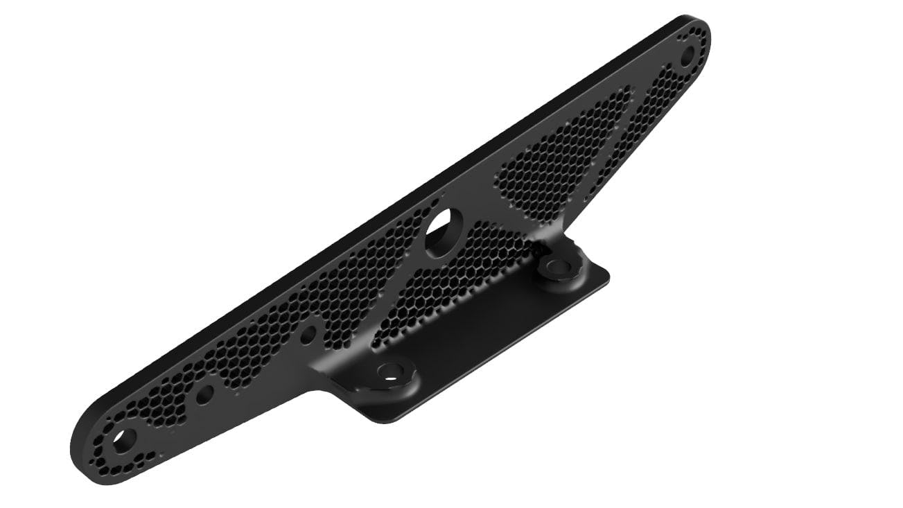
This aircraft elevator bracket combines hexagonal perforation patterns with topology optimization and can be manufactured using CNC machining.
#7 Apply a rib grid to reinforce thin-walled parts
Rib grids conform to a surface of thin-walled parts and increase their stiffness and resistance to buckling and bending. Rib grids find widespread use in aerospace components, as well as plastic injection molded parts or metal casts or forgings. There are four main variations of rib grids.
Isogrids
Isogrid ribs use a triangular pattern that increases the structure's stiffness isotropically, distributing the load evenly and efficiently. For this reason, they are prevalent in aerospace applications.
Orthogrids
Orthogrid ribs use a square or rectangular pattern that is lighter and can provide anisotropic support.
Honeycomb grids
Honeycomb rib grids use a hexagonal pattern to create stiff structures. They are commonly used in sandwich structures, or injection molded parts to avoid warping.
Voronoi ribs
Voronoi rib grids create an organic-looking grid based on random points. Because of their unique aesthetics, Voronoi ribs find applications mainly in industrial design and consumer hardware. They are also more common in 3D printed products.
Pro Tip: Think of rib grids as a lattice that conforms to a surface. You can use the same techniques to manipulate either a volume lattice or a rib grid.
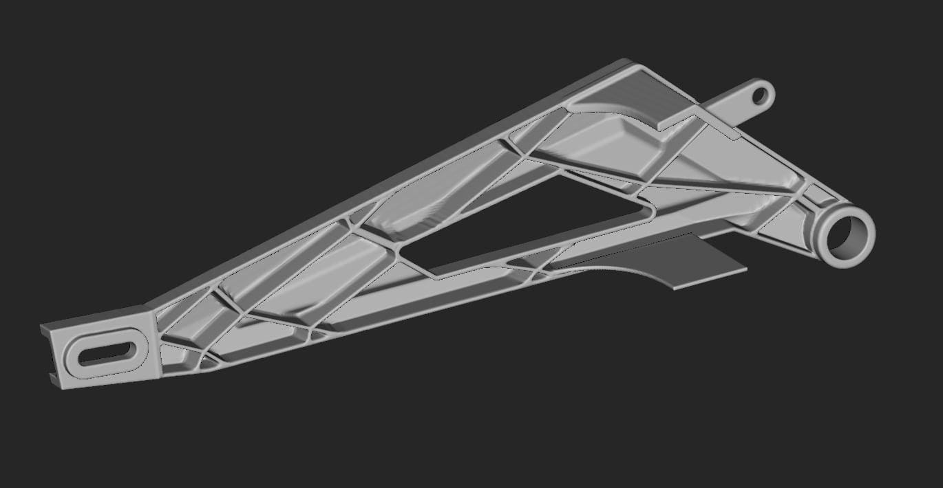
The example below shows an injection molded part. The distribution or direction of triangular ribs was modified based on topology optimization results to generate this complex rib pattern.
The distribution of ribs on this motorcycle swing arm was guided by a topology optimization study.
Key takeaways
Structural and multidisciplinary optimization combines computer methods and simulation with the designer's experience and engineering knowledge. Through smart design, you can create a finished product that is lighter and has higher efficiency, reliability, and overall quality.
Here are the three main takeaways to get you started:
- When designing for additive, begin with a simple “shell and infill” as your benchmark.
- Use topology optimization and simulation data to drive key design variables and refine your design.
- Perforation patterns and ribs are especially useful when designing for traditional manufacturing.

nTop
nTop (formerly nTopology) was founded in 2015 with the belief that engineers’ ability to innovate shouldn’t be limited by their design software. Built on proprietary technologies that upend the constraints of traditional CAD software while integrating seamlessly into existing processes, nTop allows designers in every industry to create complex geometries, optimize instantaneously, and automate workflows to develop breakthrough 3D-printed parts in record time.
Related content
- VIDEO
Topology Optimization Design for Cast and Injection-Molded Parts
- VIDEO
Lightweighting an impeller for additive manufacturing
- VIDEO
Sneak peek into the nTop + Autodesk Fusion 360 integration
- ARTICLE
Optimizing thermal management with conformal cooling to extend operational life
- CASE STUDY
Designing a cooler camera housing