How to design and optimize a patient-specific additively manufactured hip implant stem
Written by Younes Chahid
Published on April 27, 2020
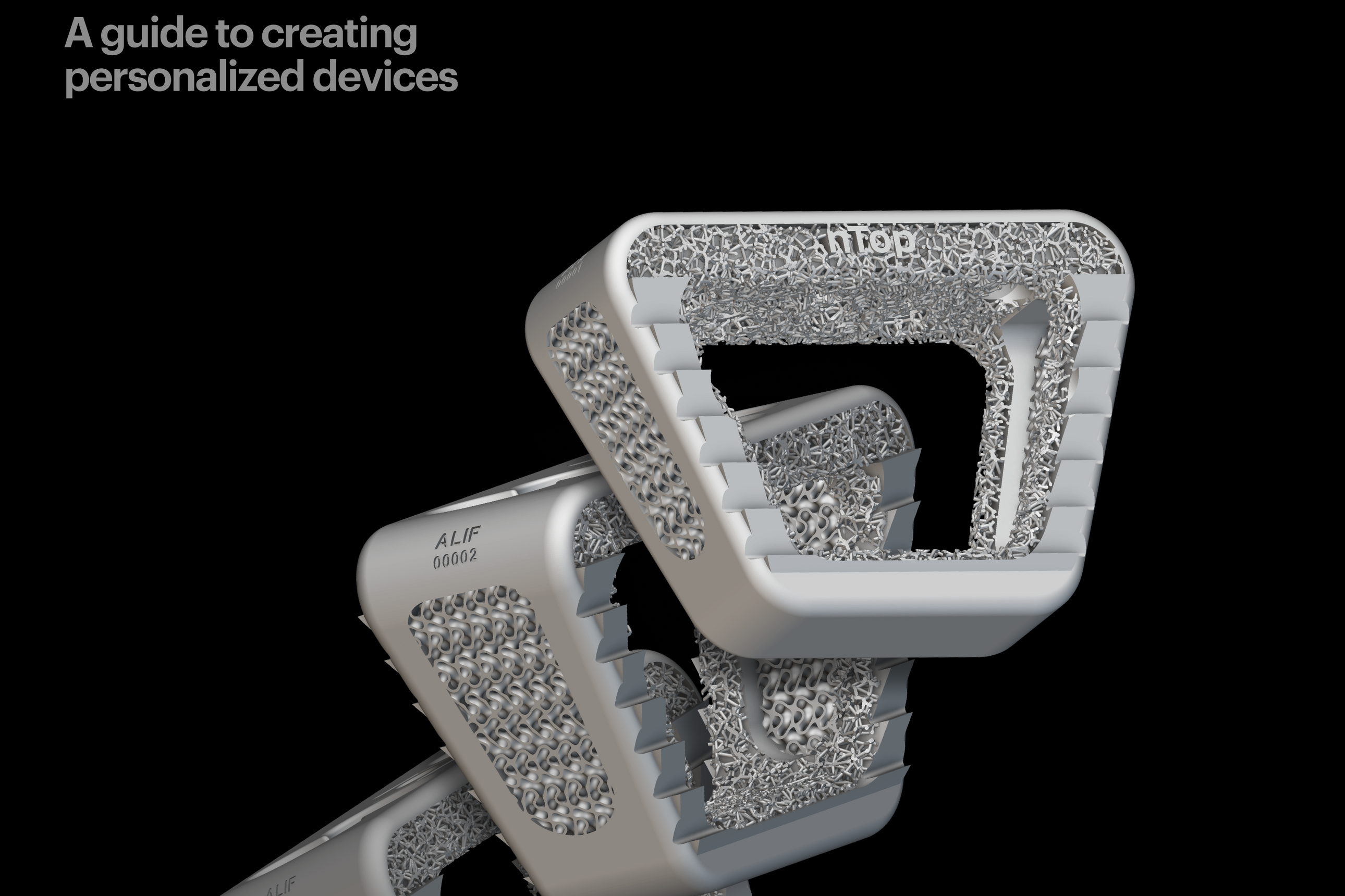
Read on to see how a student used nTop to design a novel hip implant stem and won an award for his design.
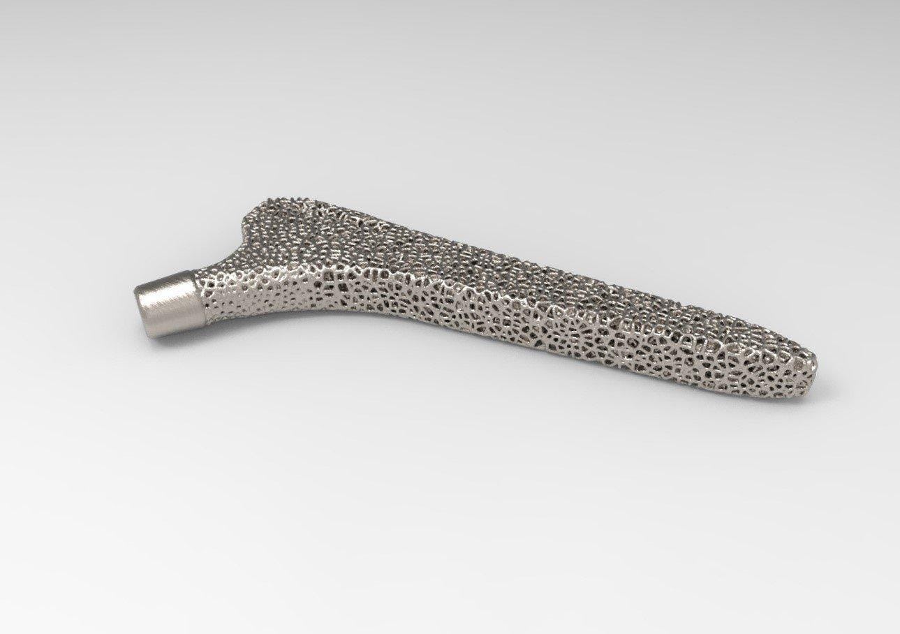
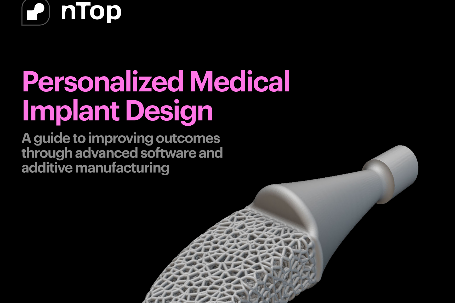
Figure 1: AM optimised hip implant stem design in Ti-6Al-4V. Winner of the 2020 Additive World student category DfAM challenge.
The advancement of Additive Manufacturing (AM) is allowing us to materialise ideas and designs previously thought impossible to manufacture. Combined with the spirit of Biomimetics, which can be described as the art and science of mimicking biological systems or nature in general, a user can run a custom experiment with specific constraints to then run a tiny “natural selection” lab, all using a laptop.
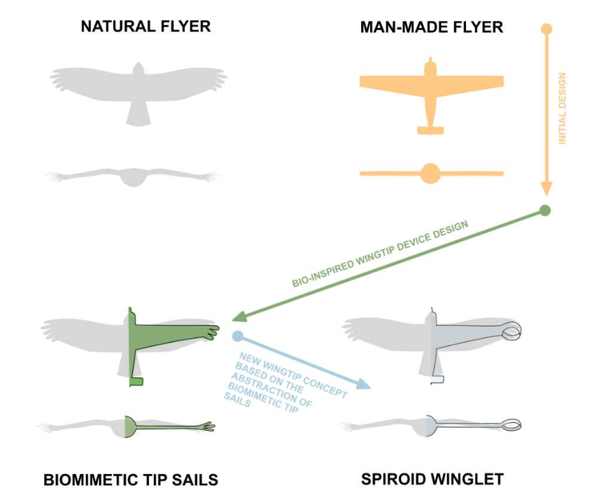
Figure 2: Spiroid winglet design through biomimetics abstraction [1].
Traditional hip implant design problems
Traditional hip implant stem designs usually cause stress shielding, meaning that they absorb most of the load that the body exercises on the hip joint. This means that lower bones in the body stop receiving their usual load and start resorbing or shrinking due to Wolff’s law. This causes the hip implant to start dislocating, leading to another surgery.
Solving that problem
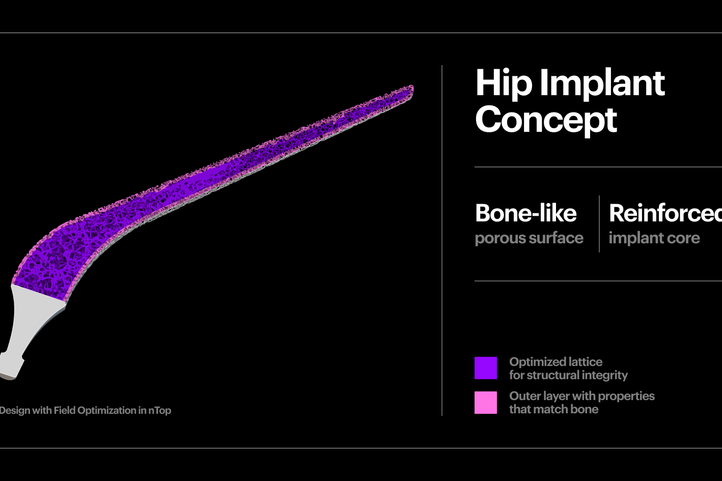
To solve this challenge, the goal was to design a hip implant stem that is as close as possible to the human trabecular bone, allowing for both the reduction of stress shielding effect and increasing the chance of osseointegration.
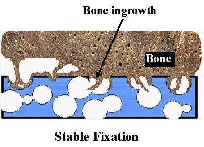
Figure 3: Bone ingrowth in a foam like structure [2].
Using nTop and beginning with a full stem (Figure 4 a), the design was initially converted to a stochastic Voronoi pattern (Figure 4 b). After applying a structural analysis in Simsolid software, the stress color scale map was then used as an input to vary both the density distribution (Figure 4 d) and the thickness distribution in a linear way (Figure 4 e). This resulted in a design that can absorb more load by sharing it through its connected lattice struts thereby avoiding a concentration of stress and decreasing the possibility of a second surgery.
The final design has an average pore size of 1.1 or mm, increasing the chances of osseointegration which usually happens in pore sizes between 0.64 mm and 1.4 mm [3]. In comparison with the initial full stem (Figure 4 a), the final design allowed for a reduction of Maximum Von Mises Stress by 23%, Maximum Displacement of 15%, and total volume of 30%. The final design (Figure 1) takes full advantage of AM capability in manufacturing custom, internal lattice structures impossible to achieve any other way, while reducing both lead time and manufacturing waste and increasing patient success.
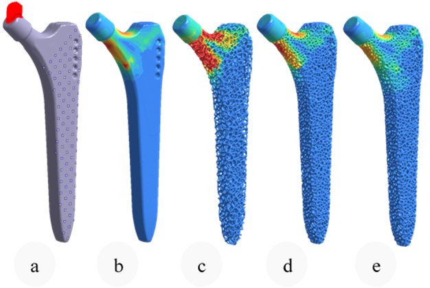
Figure 4: Same Von mises color scale from Simsolid FEA. Boundary conditions (0), initial stem FEA (1), Stochastic lattice FEA (2), Optimised density (3), Optimised strut thickness (4).
How to achieve patient-specific implants
AM allows for a parametric way of design and opens the door for a future of mass customization, but at the same time, it creates more challenges and sometimes represents a nightmare for quality control engineers and for the metrology field in general. A field that is not adapted yet to mass customization, internal features, high surface roughness and sometimes random porosity.
For this reason, a significant part of my research lays in developing or testing new inspection tools for the metrology and quality validation of AM lattice structures. I use an industrial Computed Tomography (CT) machine due to the presence of internal features that cannot be viewed using traditional tools. While not fully standardized or traceable, industrial CT machines and applications have been improving at a great pace, assisting in performing a range of measurements like wall thickness (example in Figure 6), porosity analysis and sometimes even extracting areal surface roughness parameters.
Finally, design software like nTop allows for designing lattice structures in a dynamic and parametric way. For this example, by using blocks and notebooks, a whole workflow can theoretically be built from the import of the patient CT to designing and validating hundreds of designs, to finally reach one that works specifically for the concerned patient while respecting design for AM (DfAM) rules and metrology ones.
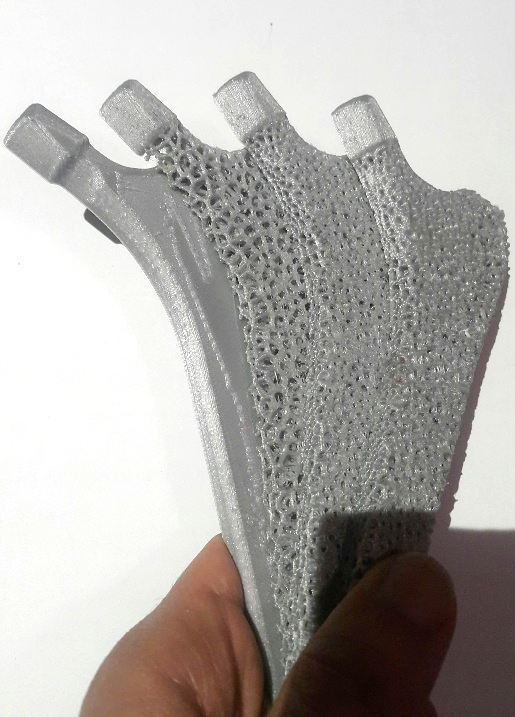
Figure 5: Prototyping a sectioned version of the design steps shown in Figure 4 using FDM technology.
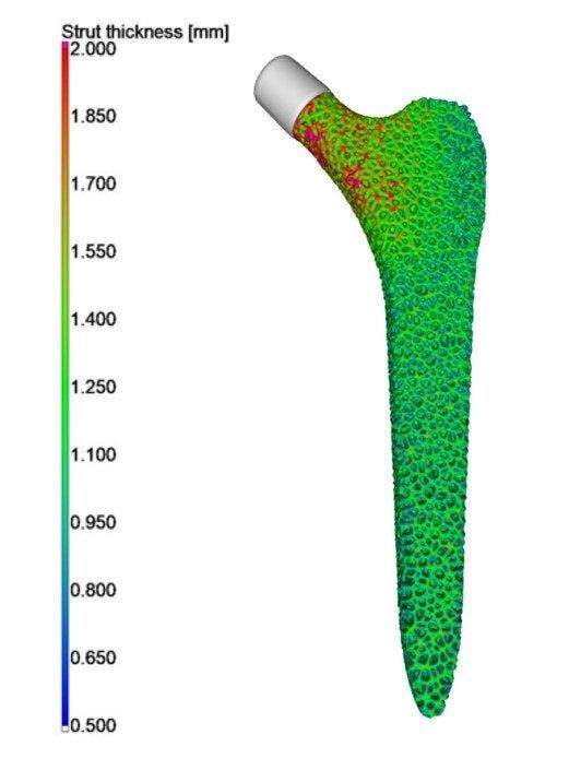
Figure 6: Strut thickness distribution of the optimized stem. (Dataset from Younes Chahid – Analysis by Philip Sperling Vgstudio).
References
[1] J.E. Guerrero, D. Maestro, A. Bottaro, Biomimetic spiroid winglets for lift and drag control, Comptes Rendus Mécanique. 340 (2012) 67–80. https://doi.org/10.1016/j.crme.2011.11.007.
[2] A. Nouri, P.D. Hodgson, C. Wen, Biomimetic Porous Titanium Scaffolds for Orthopedic and Dental Applications, Biomim. Learn. Nat. (2010). https://doi.org/10.5772/8787.
[3] M. Regis, E. Marin, L. Fedrizzi, M. Pressacco, Additive manufacturing of Trabecular Titanium orthopedic implants, MRS Bull. 40 (2015) 137–144. https://doi.org/10.1557/mrs.2015.1.

Younes Chahid
Younes Chahid has a first class Mechanical Engineering degree and is currently a final year PhD student on the topic of Design and Metrology of AM Lattice and Trabecular Structures at the University of Huddersfield. Younes has been selected in iMeche 2019 Rising Stars list and is also the winner of the international Additive World Design for AM 2020 challenge. Younes is also the founder and mentor of the award-winning University of Huddersfield 3D Printing Society. His experiences are in generative design, design for AM using topology optimisation, lattice structures and metrology using X-ray CT for dimensional, surface roughness and porosity analysis.
Related content
- GUIDE
Download: Advanced design software and additive manufacturing for personalized implants
- GUIDE
Download: Design Automation for Medical Devices
- VIDEO
Design a spooky Halloween candy bowl in nTop
- ARTICLE
Improving the biomechanical profile of additive hip implants with Field Optimization
- ARTICLE
Design at scale with nTop Automate