Meshing in FEA, CFD and manufacturing
Written by nTop
Published on June 8, 2021
Accurate mesh generation is a critical step of every engineering design workflow that involves FE analyses, CFD simulations, or Additive Manufacturing. Here, we give you practical tips and design considerations for meshing parts with complex geometries, like lattice structures, using nTop’s powerful meshing capabilities.
Applications
- General
Key Software Capabilities
- Simulation
Meshing complex geometry is one of the most critical factors for simulation and manufacturing. However, there is a delicate balance between generating an accurate mesh and creating a file that is too large for practical application. In this article, we share practical tips to generate robust meshes for parts with complex geometries.
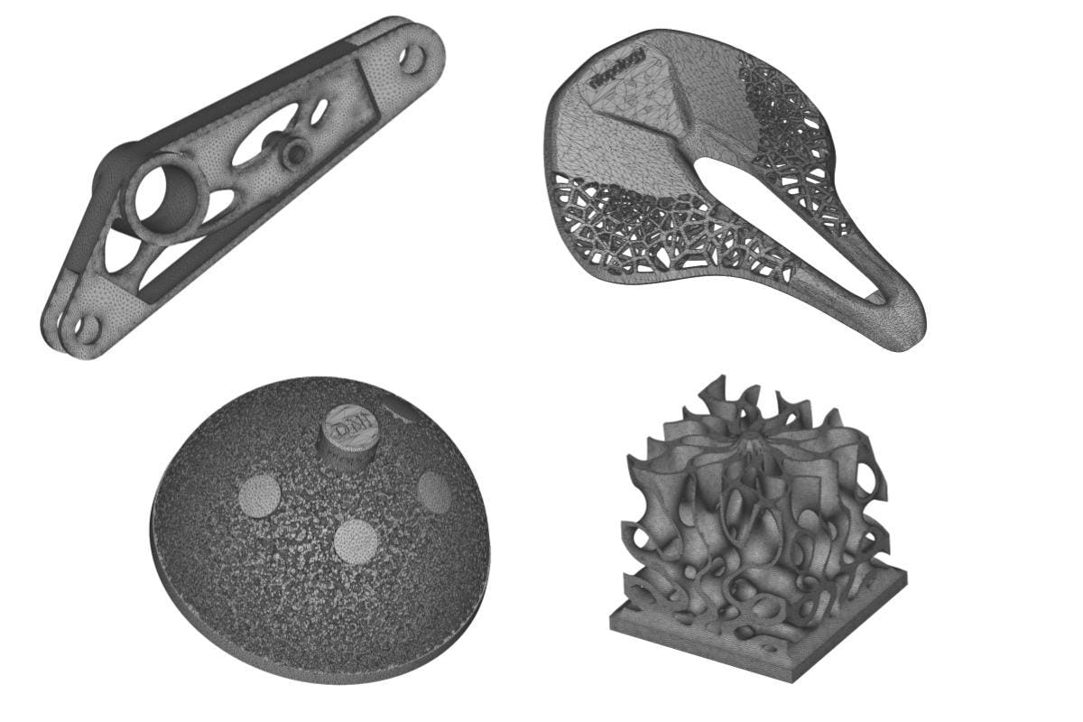
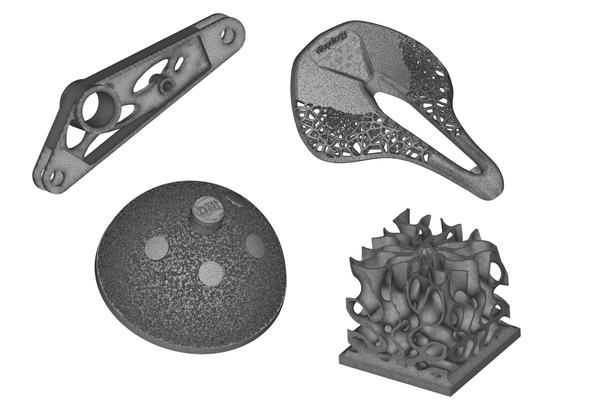
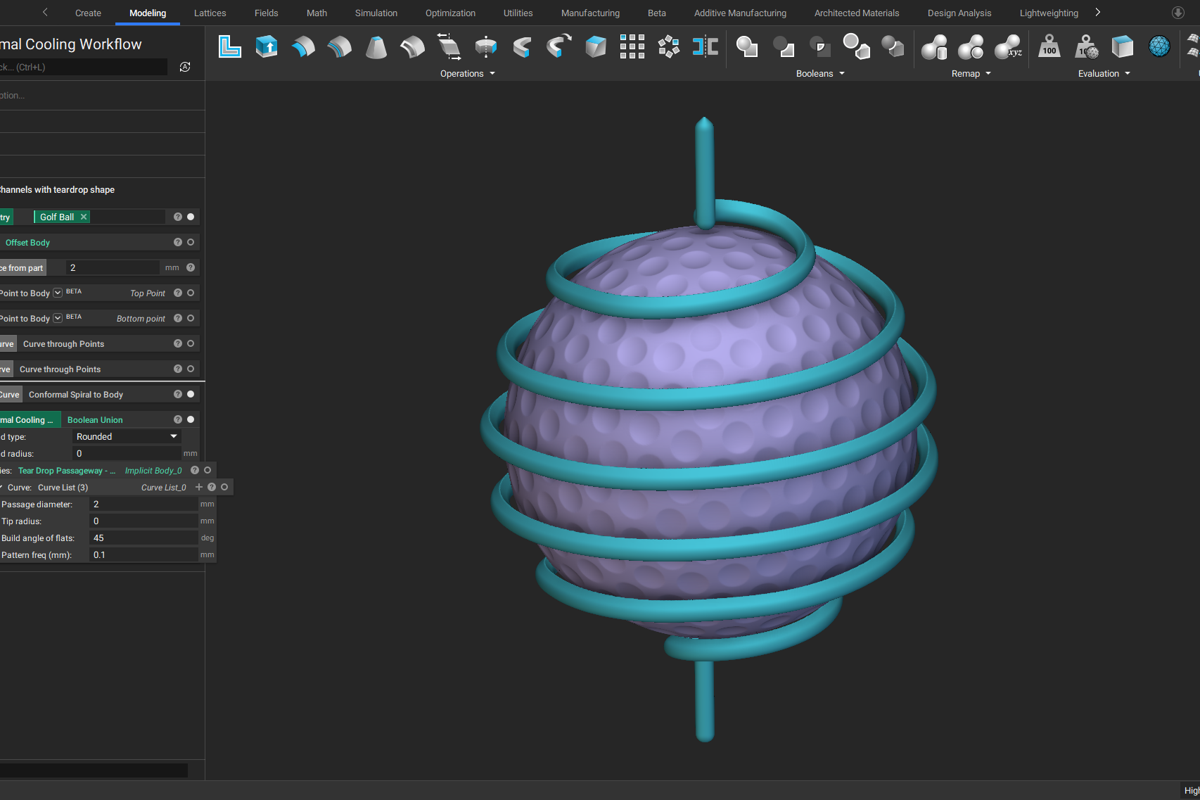
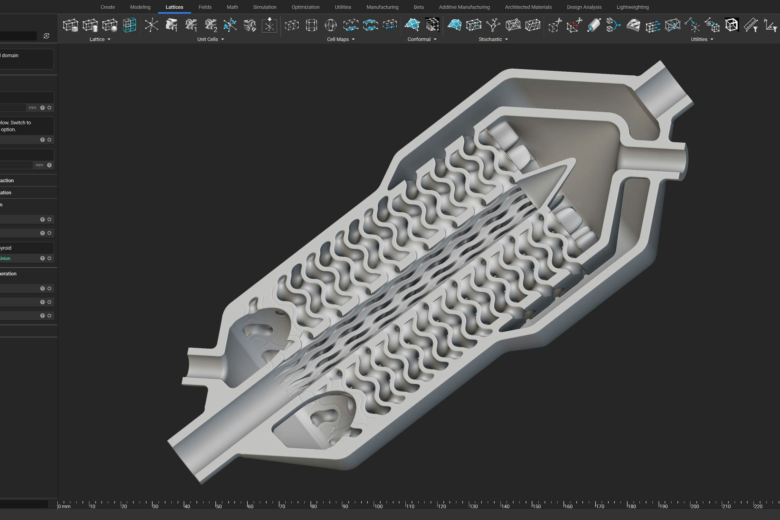
A selection of meshes of parts with intricate lattices, gyroid structures, and topology optimized shape generated in nTop.
What is meshing?
Meshing is the process of dividing a 3D model into thousands of elements to properly define its shape — the more detailed the mesh, the better the approximation. Meshes are used to run engineering simulations, communicate manufacturing data, or for rendering.
There are two main types of meshes: surface meshes and volume meshes:
- Surface meshes use two-dimensional elements — typically triangles or quads — to approximate the outer surface of a 3D body. Surface meshes are used in manufacturing or rendering applications and CAE simulation.
- Volume meshes, also known as solid meshes, use three-dimensional elements — typically tetrahedrons, hexahedrons, and polyhedrons — to define both the surface and interior structure. Surface meshes can be converted into volume meshes to run FE or CFD simulations.
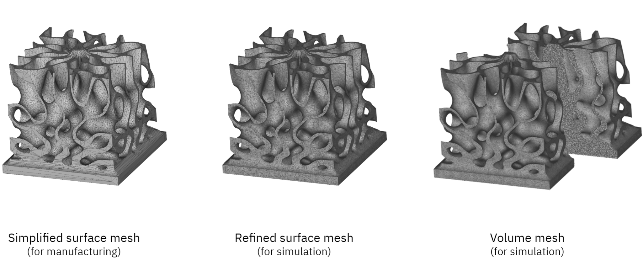
Simplified meshes are suitable for manufacturing, while more refined meshes are more suitable for FEA and CFD and can be converted into a volume mesh.
Why is meshing important in FEA and CFD?
Meshing is integral to computational simulation techniques, like the finite element method (FEM) and computational fluid dynamics (CFD). Simply put, FEA or CFD simulations are not possible without a mesh.
Meshes discretize a continuous geometric space into predictably shaped and mathematically defined elements. This discretization enables computers to numerically solve the underlying governing equations and simulate the physical effects. The mesh quality influences the accuracy, convergence, and speed of the simulation process.
Why is meshing important in manufacturing?
Meshes are used to communicate manufacturing data. Meshes are often considered a necessary evil in manufacturing. For example, the STL file format is a mesh with triangular elements that describe the surface of a solid body.
Today, STLs are the predominant file format for sharing part data for additive manufacturing. However, many have criticized this file format because it falls short in conveying other essential manufacturing information. In addition, it introduces an unnecessary data conversion step that can potentially reduce accuracy.
Design considerations for meshing complex parts
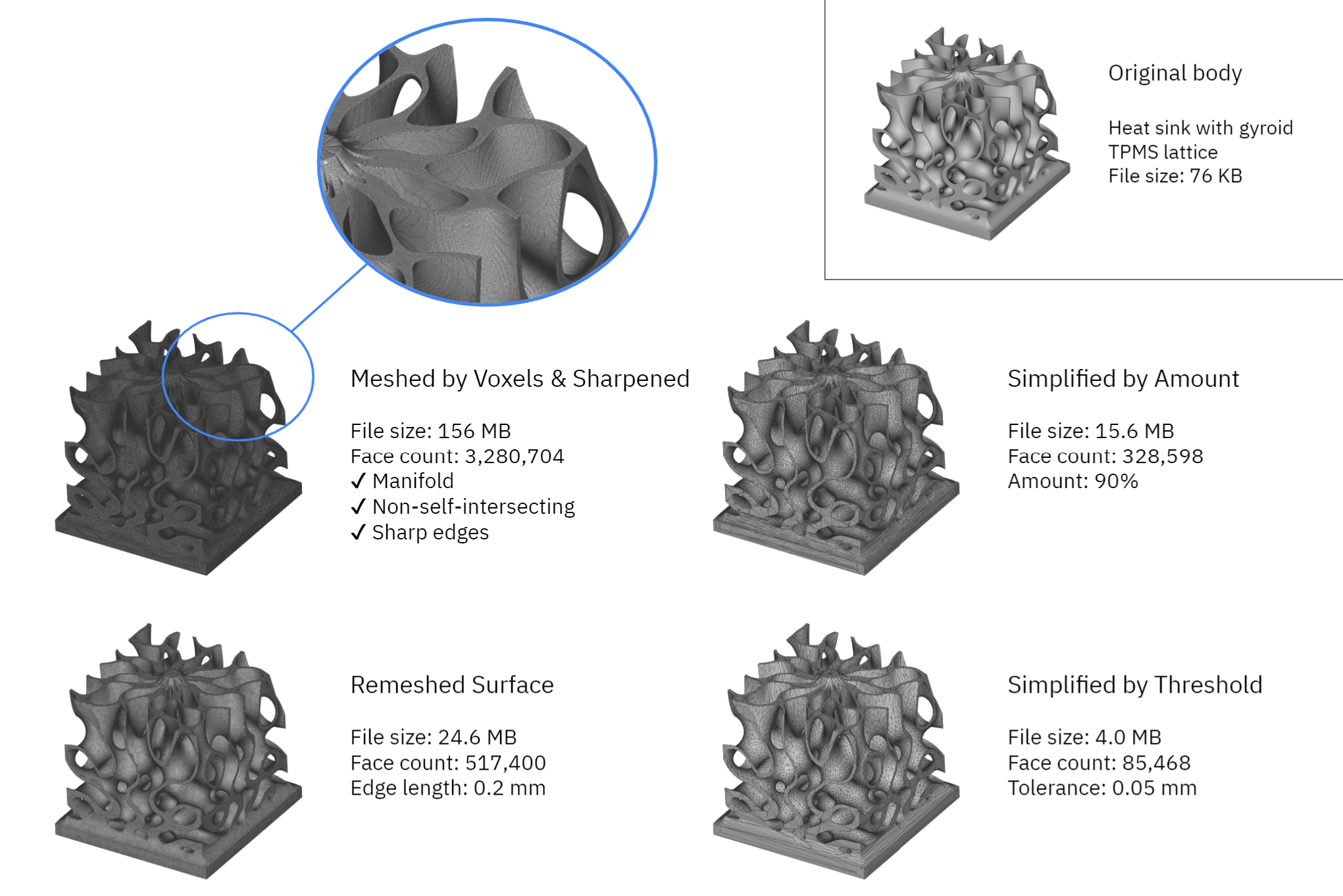
Comparison of mesh metrics post-processed to different levels of fidelity. All meshes were exported as STL. Note that the OBJ and 3MF file formats offer higher levels of compression and may result in smaller file sizes.
Independent of your application, a high-quality mesh needs to be:
- Error-free (i.e. manifold, oriented, and non-self-intersecting)
- Detailed enough to produce accurate simulation results and ensure tolerances
- Not too detailed to make the file size unmanageable
The best meshing parameters depend on the intended application. For example, a very fine mesh captures more accurately the 3D geometry, allowing for higher fidelity simulations. However, it also produces a larger file size; as a rule of thumb, halving the grid size increases its file size and the time it takes to compute by a factor of 4x to 8x.
There is no need to spend additional computational resources when the same result can be achieved with a simpler mesh.
When meshing the user must balance computational resources and the intended use of the geometry. This trade-off is especially relevant when generating meshes for parts with complex geometry, such as lattices and organic shapes. These geometries require more elements to capture the intricate part features and curved surfaces accurately.
Meshing in nTop
Generating a mesh in nTop is configurable and (potentially) fully automatic. nTop offers a range of configurable meshing tools that enable you to build reusable meshing processes and modify them to your application.
What is the meshing process?
The mesh generation process in nTop begins with creating a surface mesh from an implicit body. The surface mesh can then be post-processed, remeshed, coarsened, exported as an STL or 3MF for manufacturing, or converted into a volume mesh for simulation.
Remember that every meshing operation is essentially a discretization operation that approximates the intended 3D geometry. The goal is to fit mathematically-well-defined mesh elements to a 3D body while minimizing the overall error while making sure that all elements connect properly to each other.
Mesh from implicit body
The Mesh from Implicit Body is exceptionally robust and produces error-proof meshes even for the most complex geometries. It also introduces the concept of tolerances in mesh generation, which is a more intuitive way to select meshing parameters.
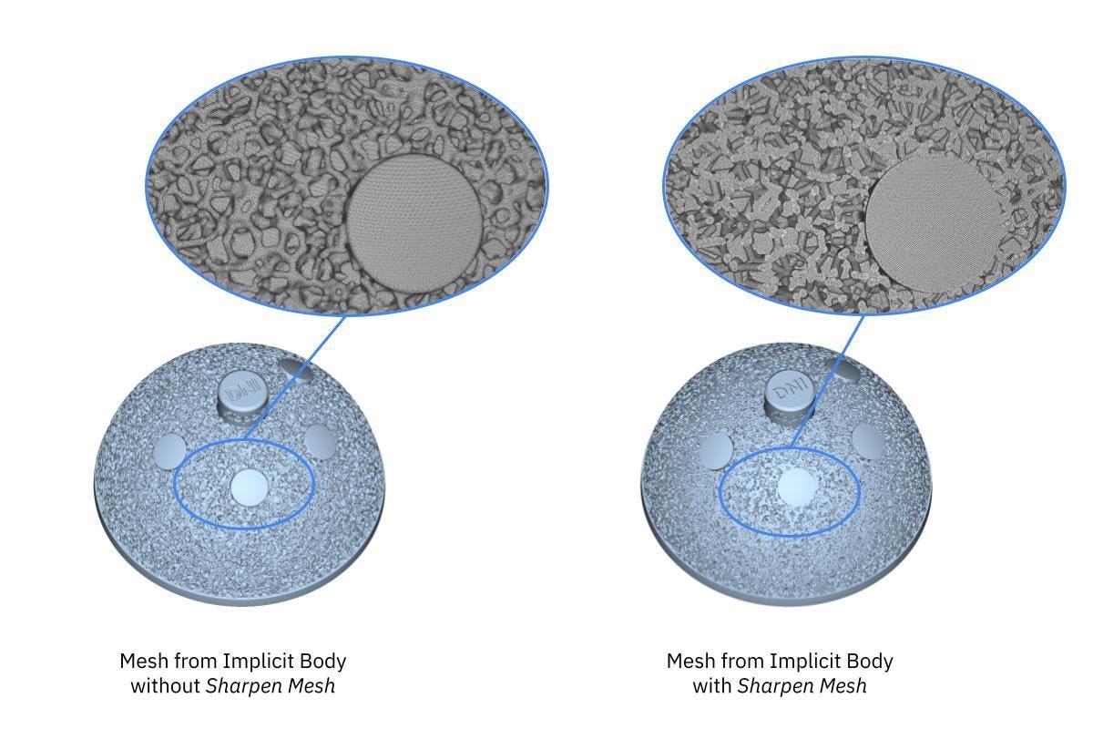
The Sharpen Mesh option can be used to capture details of intricate meshes produced with the Mesh by Implicit Body.
Benefits
The Mesh from Implicit Body is exceptionally robust and produces error-proof meshes even for the most complex geometries. It also introduces the concept of tolerances in mesh generation, which is a more intuitive way to select meshing parameters.
Limitations
The output of this block tends to remove sharp edges. This is usually acceptable for parts with no sharp edges or manufacturing but can cause inaccurate simulation results, such as running an analysis on geometry with sharp features.
To overcome this limitation, we can either reduce the tolerance value (increasing computation time) or use the Sharpen Mesh option to restore sharp edges. This option runs an intelligent reconstruction algorithm that identifies the sharp edges in the original model and adjusts the position of the mesh nodes and vertices accordingly to capture these edges.
Recommended settings
As a starting point, it is recommended to use a tolerance equal to 0.5 times the thickness of the smallest feature. This value will typically exceed the accuracy of most additive manufacturing processes. If you plan to sharpen the mesh, avoid the simplify and remeshing options of this block.
A single iteration will usually produce good results when using the Sharpen Mesh option. Still, three iterations are recommended, especially if you are preparing a mesh of a complicated model for simulation. Without enough sharpening iterations, you may end up with too many small elements that can cause issues during remeshing. Jump to the next section for more practical meshing tips and rules of thumb.
Mesh post-processing
Simplified meshes are suitable for manufacturing use-cases, while remeshing is necessary for simulation purposes.
In nTop you will find many meshing tools that can help you better prepare for downstream operations. Here are three of the most helpful mesh post-processing blocks.
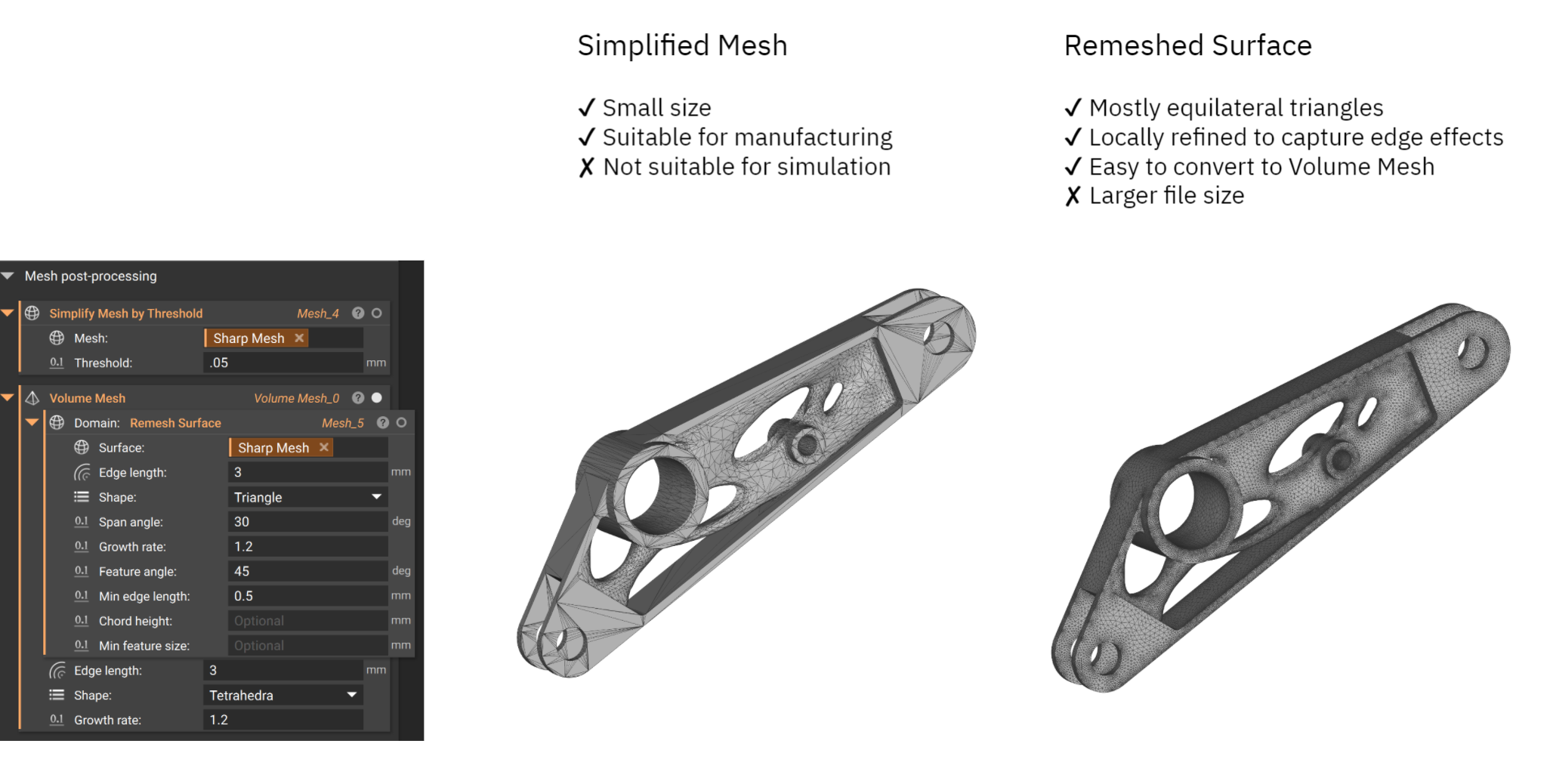
- Remesh Surface: The mesh generation blocks in nTop do not produce mesh with an exact element size. This block can be used to create a mesh with explicitly chosen properties using triangle or quad elements. Remeshing comes in handy when you need to control the mesh properties and prepare them for simulation.
- Simplify mesh by Threshold: This is an easy way to reduce the file size of a mesh for manufacturing. This block will create the mesh with the least amount of faces. A good starting point for the threshold is 1/4 to 1/8 of the manufacturing tolerance.
- Simplify mesh by Amount: This block generates a mesh that is smaller than the original based on the specified amount. For example, a value of 0.9 will create a mesh with 90% fewer faces, and as a result 90% smaller file size.
- Volume Mesh: This block converts a surface mesh into a volume mesh. This is a necessary step before FEA or CFD simulations. We recommend using the Remesh Surface block using a triangle mesh before converting it into a solid tetrahedral mesh.
Meshing tips and rules of thumb
Creating a high-quality mesh is not a straightforward process. The optimal parameters depend on object geometry and the intended use. However, the following tips will put you in the right direction.
Preparing meshes for additive manufacturing
The optimal mesh size depends on the minimum feature dimension and the achievable tolerance of your manufacturing process.
Most additive manufacturing systems produce parts with a feature tolerance of ± 0.1 to 0.2%. For this reason, a tolerance of 0.2 mm or 50% the thickness of the smallest feature for the Mesh from Implicit Body block is a good starting point. This value typically produces a good trade-off between accuracy and file size.
The Simplify Mesh by Threshold is particularly useful for minimizing the file size for manufacturing. It is recommended to use a threshold value within your manufacturing tolerance.
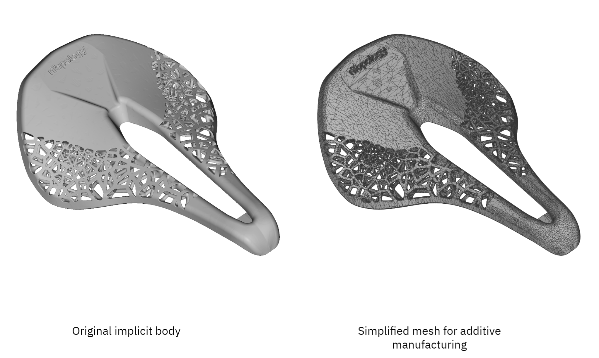
A coarser mesh with sufficient tolerance produces a good trade-off between accuracy and file size.
Preparing meshes for simulation
The finer the mesh, the more accurate results the simulation will produce and the longer it will take to complete.
Ideally, we recommend running a mesh convergence study to identify the optimal mesh size. In a mesh convergence study, we repeat the simulation with progressively finer meshes until there is no significant difference in the response.
However, this process is not always practical, as meshing typically consumes a significant portion of time. We can use nTop’s design automation capabilities to save manual design time.
The following settings for the Remesh Surface block and the Sharpen Edges option are good starting points for meshing any complex geometry before performing an FE or CFD simulation.
Growth rate
Use a Growth rate between 1.2 to 1.5 — this is the industry standard for FEA and CFD. The growth rate dictates how smooth the transition between the finer and coarser areas of the mesh allows us to capture edge effects better.
Edge length
Use an Edge length that is best suited for the simulation that you are performing:
- Thermal FE: An edge length equal to the wall thickness is sufficient.
- Structural FE for deflection analysis: Use an edge length ≤ 1/3 of the wall thickness.
- Structural FE for stress analysis: Use an edge length ≤ 1/5 of the circumference of the smallest fillet, hole, or other transition to capture edge effects.
- CFD for fluid analysis: Use an edge length that is ≤ 1/7 of the wall thickness to properly simulate fluid flow.
Pro Tip: The edge length is not the only way to control fidelity. Span angle, growth rate, and chord height are other control options that can improve the accuracy of a mesh. In practice, you can set a much larger edge length that you need, and then the software will locally calibrate that value to fulfill the other requirements you’ve specified. Doing so can significantly reduce the time to mesh.
Original mesh size
The Remesh Surface solve time is highly dependent on the number of input elements. So we can use the Simplify by Threshold or Amount to reduce the incoming element count before this block.
Pro Tip: Our benchmarks tests have shown that you can achieve a Remesh Surface output with approximately the same element count, even if you simplify the input mesh by an amount of up to 50%.
Mesh sharpening
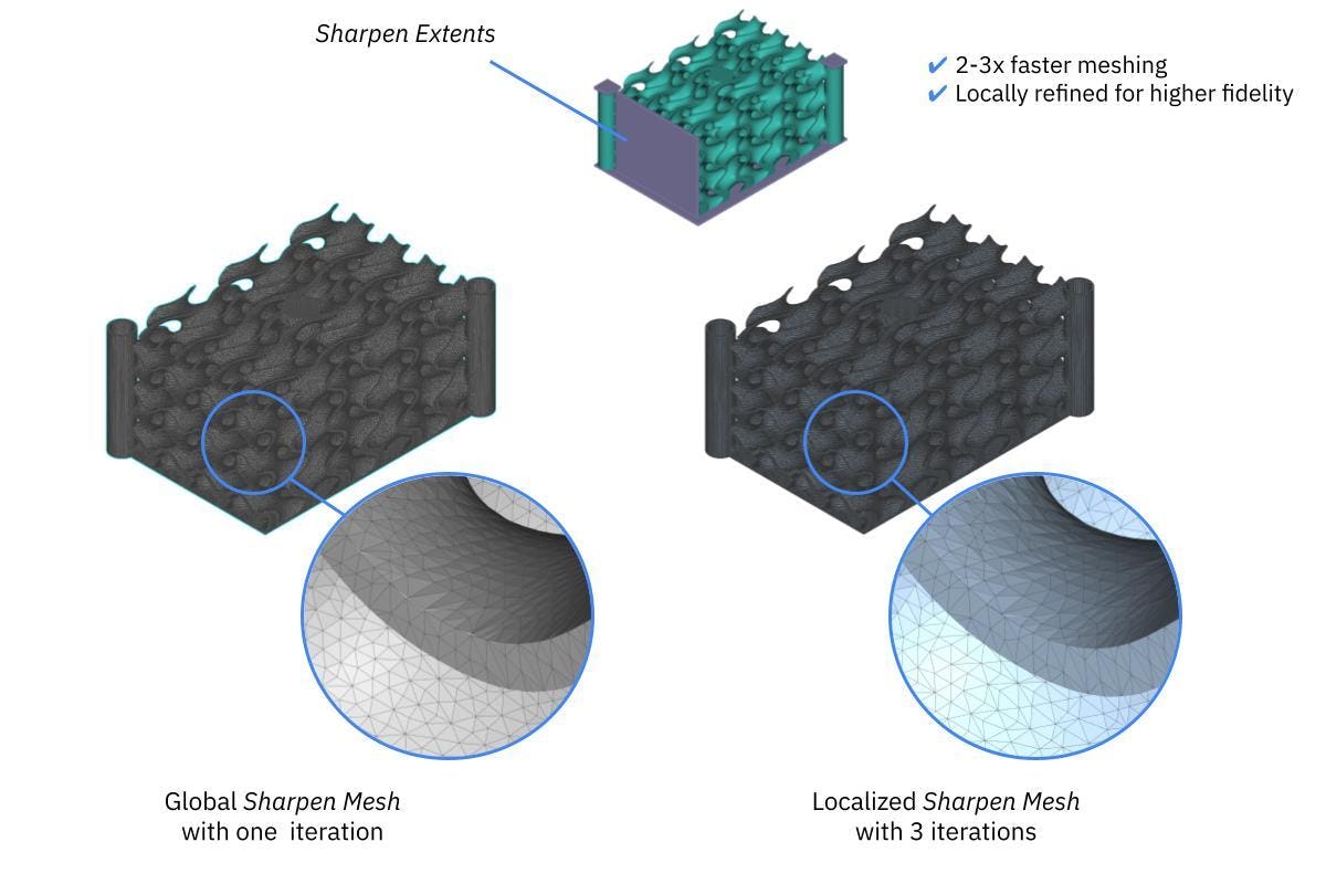
Localized sharpening can help you generate high-fidelity meshes faster.
Generally, three sharpening iterations are recommended for simulation. Without sharpening, you may end up with too small elements in a complex model that can cause issues during remeshing.
Pro Tip: When using the Sharpen Mesh feature, we often don't need every single edge in our model to remain sharp. Generally, we are concerned with specific regions, such as the areas where we apply boundary conditions for analysis or where we have GD&T requirements for machining, assembly, and various other applications.
nTop gives you the option to sharpen only specific regions using the Sharpen Extents to avoid sharpening the whole mesh. This option helps decrease the time spent meshing by 2x to 3x and the overall element count.
Key takeaways
Accurate mesh generation is a critical step of every engineering design workflow that involves FE analyses, CFD simulations, or Additive Manufacturing.
With nTop’s recent meshing enhancements, nTop users can generate high-quality meshes using automated workflows. Using this article’s tips and nTop’s robust and automated meshing tools should set you on the right path.
Here’s what you need to remember:
- An overly refined mesh unnecessarily increases file size and wastes computational resources and time. Find a balance between accuracy and speed.
- Keep in mind the tolerances of your manufacturing process when coarsening the mesh for 3D printing.
- Adjust the mesh parameters using Remesh Surface and locally sharpen critical areas to prepare the mesh for simulation.

nTop
nTop (formerly nTopology) was founded in 2015 with the belief that engineers’ ability to innovate shouldn’t be limited by their design software. Built on proprietary technologies that upend the constraints of traditional CAD software while integrating seamlessly into existing processes, nTop allows designers in every industry to create complex geometries, optimize instantaneously, and automate workflows to develop breakthrough 3D-printed parts in record time.
Related content
- VIDEO
Five ways to lightweight in nTop
- VIDEO
Sneak peek into the nTop + Autodesk Fusion 360 integration

- ARTICLE
Optimizing thermal management with conformal cooling to extend operational life
- ARTICLE
Advancing structural performance of aerospace heat exchangers
- VIDEO
Design a spooky Halloween candy bowl in nTop